
Isuzu Trek Members Infoletter #46
October 2023
Welcome to Isuzu Trek Infoletter #46.
The I-Trek infoletter mailing list is managed in a Google Group: (https://groups.google.com/forum/#!forum/i-trekinfoletter). If you would like to be included in this exclusively Isuzu Trek group please request inclusion in our mailing list or e-mail the editor Bret Medbury for info at isuzutrek (at) gmail.com or islandduo (at) comcast.net. If you would like more detailed/higher resolution photos of any of the included ones please e-mail the original creator.
You should all be aware that a fantastic new resource for I-Trek owners has been added to the treasure trove of info on the Northwest Trek Fun Club website. Finally, with the help of John Herold NWTFC Webmaster, “we” (mostly he) has gotten the complete Isuzu NPR parts list posted. www.nwtfc.com/isuzu-infoletters/isuzu-trek-documents/ It contains every chassis part part number, right down to the screws and wire clips. My experience sez once you have a correct part number you can find the part. It is a large PDF file; I suggest you download it once then just keep it on your computer for ready access.
Wow has it been a challenge for me to get this put together and out to all of you. We had just such an enjoyable and active winter after the Quartzsite gathering, then, in March, spring got in the way back at home, well then just life got in the way. Whew
Well here we are, please learn and enjoy.
Index:
No power to Driver’ Seat
Sulaiman
Exhaust Pipe Bracket Broken Bolt
Sulaiman
Crack in Propane Tank Heatshield
Sulaiman
Furnace cover Louvers
Sulaiman
Exhaust Manifold Bolts (again)
Sulaiman
Upgraded/replaced Front and Rear Clearance Lights
Ken
Isuzu Airbag Suspension
Bruce
Great Source for Window Parts
Denney
1992 Isuzu Trek Rear View Camera Upgrade
Jim
It is wonderful how the Trek family works
Henry
Norcold Overtemp Switch Failure
Bret
Updated/Corrected Alternator wiring diagram
Dick
Truly High Tech Cruise Control
Dave
Water Heater Cover Retrofit
Sulaiman
No Power to Drivers Seat:
Sulaiman Kahn
sulaik(at) yahoo.com
I use to have power but it just quit working all of a sudden. I traced the problem to a bad connection at the power connector under the driver’s seat. It appears that someone had this problem before but did not fix it. I think what happened was the ground wire broke at the terminal of the connector. So rather then removing the terminal and re-connecting (solder) the wire back to the terminal they just got a spade lug, crimped it to the wire, jammed it into the connector with the old terminal still in place and wrapped it with electrical tape. Anyway when I took a closer look at the connector and saw the electrical tape, I knew then something was fishy.
I removed the terminal, took out the old wire that broke, crimped and soldered the ground wire back and pushed it back into the connector. I have power seat again, Yeah!
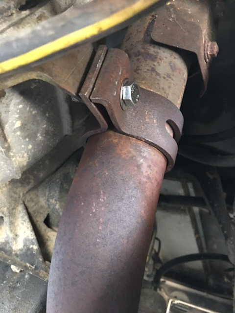
Exhaust Pipe Bracket Broken Bolt:
Sulaiman Kahn
sulaik(at) yahoo.com
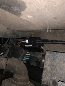
I have this annoying sort of high pitch rattle that appears to be coming out of the box that houses the gear shift. Sounds like a tiny washer in a tin can and the tin can is vibrating and washer is vibrating at the bottom of the can. While under the Trek trying to find where this rattle is coming from I noticed that the exhaust bracket had slipped down the exhaust pipe coming from exhaust header. What happened is that the bolt holding bracket broke. Here is a before and after fix picture. Other Trekers my want to check their bracket bolt. After this was fixed, I still have the rattling noise.

Crack in heat shield between propane tank and exhaust pipe:
Sulaiman Kahn
sulaik(at) yahoo.com
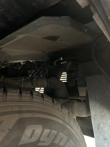
Again, still looking for the source of this annoying rattle I noticed the heat shield panel between the propane tank and exhaust pipe had some cracks. Moving the panel did make a noise similar to the rattle I am trying to find. Here are the before and after pictures of the temporary fix. No more rattle when the panel is moved but it was not the source of the rattle I was looking for.


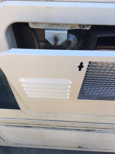
Furnace cover louvers:
Sulaiman Kahn
sulaik(at) yahoo.com
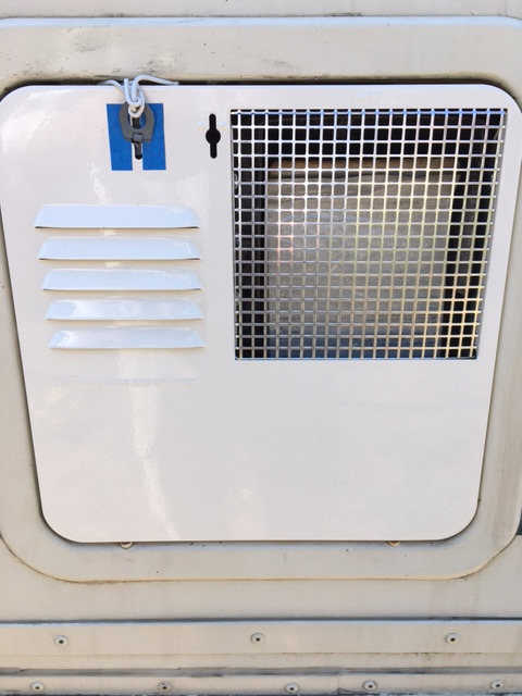
It was always not aesthetically pleasing to step into the motor home as see through the louvers which was facing upward which exposed the metal box behind it. This is right below the fridge. I flipped it, had to move the metal pieces for the magnets, it was not just a simple flip. Here are before flip and after flip pictures. BTW, what is this box behind the louvered panel? Is it a heater? If not than the title of this section is incorrect.
Editor’s Note: Yes it is the Suburban furnace/heater. I suspect that whoever installed the wood floor got it upside down. Your “fix” is the way it was from the factory.


Exhaust manifold bolts
Sulaiman Kahn
sulaik(at) yahoo.com
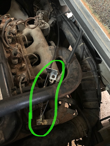
I finally go to the bolts. I removed the back one (cylinder 4 top). It came off real easy which makes me worry. Some pictures below. It does not appear that it broke. I looked inside the hole and could not see anything broken in there. I was able to insert thin piece of metal and it went in deeper than the bolt by another 1/4 inch. The current head of the bold and washer is 3/8 inches, so I think I am safe. I can buy a stud that is 2 1/4 to 2 1/2 long from Napa along with a flat and lock washer. There is no lock washer on the current bolt so I think it just worked it’s way loose. I am doing one bolt at a time as you recommended. Some time this week I should be able to buy 4 studs with nuts,


Editor’s note: Sulaiman did complete the replacement of the four outer exhaust manifold bolts with studs and nuts. I should mention that the very thick washers shown in these photos should be retained or replaced with new thick and hardened washers. Hardware store washers are not up to the task, lock washers are not needed or recommended. Replacing these bolts with studs will significantly reduce the inevitable chance of a bolt breaking as described in Infoletter #37.
Upgraded/replaced front and rear clearance lights
kastein(at) w1kas.net
Our factory clearance lights were seriously showing their age and from what I could tell, they were responsible for some not insignificant water leakage into the endcaps of our 94 2830. So I replaced them. I can’t vouch for the longevity of the exact lamps I used just yet as the rears have only been on the RV since early January and the fronts since today, but so far I like the look and fit.
Parts and tools needed:
phillips “demolition driver” (milwaukee, available at home depot)
2lb hammer
plastic razor scraper blades and holder (I used the tip of a flat blade screwdriver, but it required more care to not scratch the fiberglass than I would have liked and you should just use plastic razor blades intended for detailing and vinyl wrap + tint work.)
shop towels
non chlorinated brakleen or acetone
qty 10 #10 x 1″ stainless steel screws, pan head, per end of RV (I just bought a box of 25 at Lowes)
1/4″ diameter white dicor rope (or 1/8″ x 3/4″ ribbon, which I already had from replacing our entry door’s window: https://www.amazon.com/gp/product/B001FCB4JS/ – I folded it double so it was 1/4″ x 3/8″ and it worked alright)
qty 2 blue and 8 yellow marine grade sealant lined butt splices per end of RV
wire cutters, strippers, RBY terminal crimper, heat gun for shrinking butt splices (or blowtorch, if you’re careful enough)
lights I used for the front: https://www.amazon.com/gp/product/B00VT2Y2WA/
lights I used for the rear: https://www.amazon.com/gp/product/B00VT85Q0G/
(I would have preferred square over oval, but they look alright, and the mounting screw spacing matching exactly was much more important to me than the exact styling. If you use another lamp, make sure it is 2-15/16″ to 3″ mounting screw spacing, and two wire, as the fiberglass will not ground a one wire lamp.)
At least on our RV, the factory mounting screws were pretty badly rusted, including the threads being rusted into the fiberglass endcap. So my removal process was to use the demo driver and 2lb hammer (love taps only – don’t want to crack the fiberglass, just shock the rust loose and fully seat the screwdriver tip in the rusty screw head) to seat the screwdriver, then lean into it nice and hard while turning it. About 80% of the time this results in a horrifying pop or crunching noise and the screw coming loose and unthreading without further ado. The other 20% of the time it breaks off the head and you have to pry the lamp housing off the RV, then use vise grips to remove the stump of the screw from the fiberglass. Luckily none of them broke off flush with the fiberglass.
As you can see, the factory sealant has deteriorated worse at the top than the bottom, which results in the lamp housing funneling water straight into the wiring hole. Also, the transparent cap is not sealed to the backshell at all, and the bulb socket isn’t sealed to the backshell either, so they fill with water and then it runs through into the interior either way,


And After:


Editor’s note; dang not another!! you have seen mention here of the windshield wiper motor mounting failing due to wood rot above the windshield as mentioned in Infoletter #45. The above reseal of these lights can go a long way toward preventing that problem.
Isuzu Airbag Suspension
matlackwindsurfing(at) icloud.com
Bruce has found an airbag upgrade to improve and soften the Isuzu suspension by purchasing a kit and then having it modified to work. I am reproducing enough of the information here to act as bait for your interest. If you would like more details including contact information on his fabricator please contact Bruce directly at the above e-mail.
This rear bag assembly looks crooked but it is not. It’s the camera distortion. Rears are weld mounted on the axle on bottom; to the frame on top. Fronts are clamp mounted to the bottom, under the leaf spring assembly and to the top of leaf spring it is custom welded to the frame. Bag kits purchased from “Switch Suspension”, Phoenix, Az. DOT approved. The price may have been a sale price. Air fill nozzles: One is forward and accessed under the bumper and the one for rears is in a wheel well. The air pressure system seems to run best with 12 psi front; 25 psi aft, but I have not accurately tested range difference with pressure. Low pressure is definitely better forward or hobby horsing comes into play as if you need stronger shock absorbers.
(Note that I have had added two more leafs aft- before air bag additions, if you are into counting them and the number is different from your rig ). front bags were positioned about 5.5 inches forward of axle center to facilitate the best welding spot on the frame above the leaf spring. the only glitch was that the lower leaf spring attachment point did not stay put. it vibrated aft so that the bag assembly listed aft about 25 degrees off center. I made mahogany wood stops which solved the problem of the bag assemblies slipping aft, off center. The SS hose clamps I purchased were too large, so I used deflated tennis balls as shims and to serve as swell conversation pieces for the next owner. The epoxied mahogany shims have not moved. my head has swelled in pride from my streetwise design.


Great Source for Window Parts
denneyjones(at) gmail.com
This will be my Christmas gift to the Group. Bret you should include this in your next news letter. Excellent source for window parts. ParKin accessories 1-800-637-8938. www.parkin-acc.com. Screen clip top #109-185. Screen clip bottom #109-184. Anti rattle clip #109-467. Drain cover #009-333. Rubber window seal (sold by the foot) #009-344. I just found this information going thru my old files. I checked and the website is still active. Hope this helps!!
1992 Isuzu Trek Rear View Camera Upgrade
jseuf(at) hotmail.com
We have a 1992 Isuzu Trek 2600 with rear twins. We bought it last year and it came with the original large, low-resolution rear view camera. This camera was working, but obviously the image quality is low. Somewhere in its past the monitor was upgraded. The monitor sat top center on the dash. This location restricted how far down our EMB could lower.
I decided to upgrade both ends of the system. In theory the newer monitor could have been saved, but it had a hard-wired 4-pin mini din connector that was no longer usable (bent pins and guide post prevented a good connection).
After reading about the experiences you all shared with your Treks, I started looking at complete system kits on Amazon. all of those come with connectors that would be difficult to pair to the existing coax. Instead, I found a standalone camera and monitor that each accept RCA connectors.
They are here: Camera ($35) and the monitor ($63).
The camera is small – roughly 1” on all sides. The monitor is 7” diag. Both support 1080p, but I don’t think the RCA input I’m using supports the hi-res. The monitor also has inputs for HDMI and conventional VGA ports.
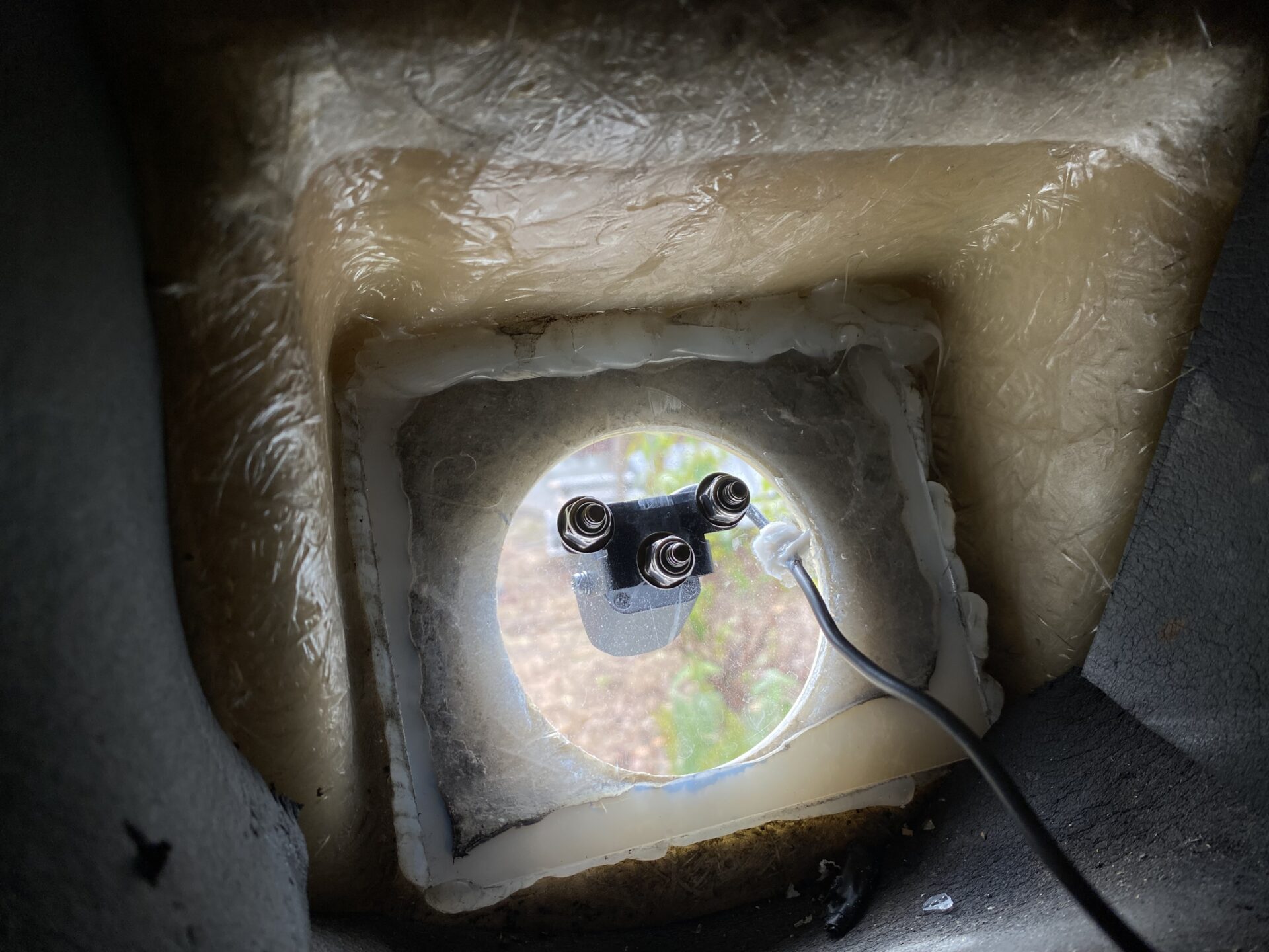
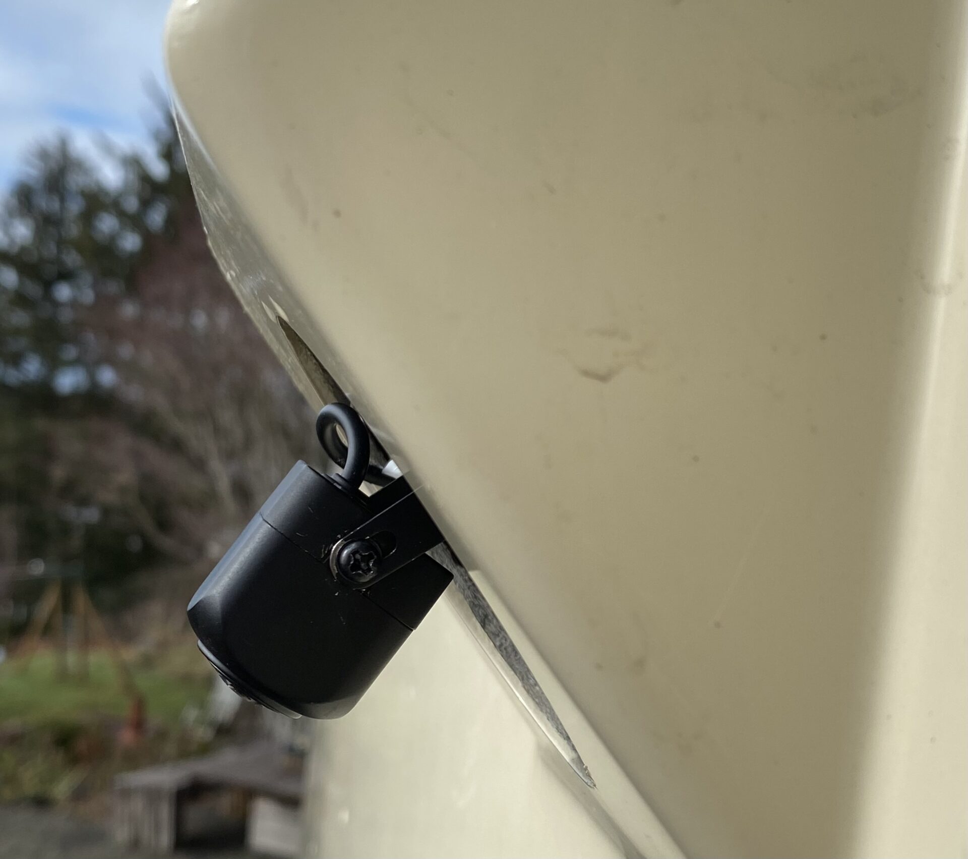
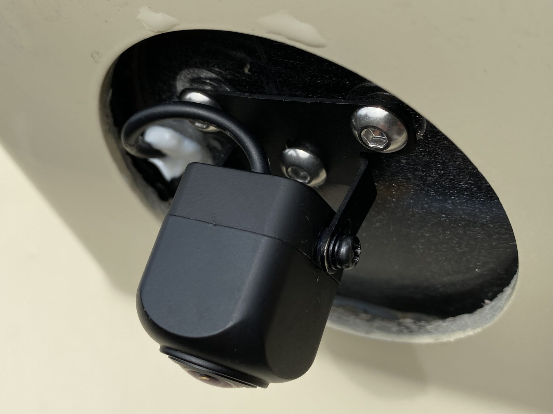
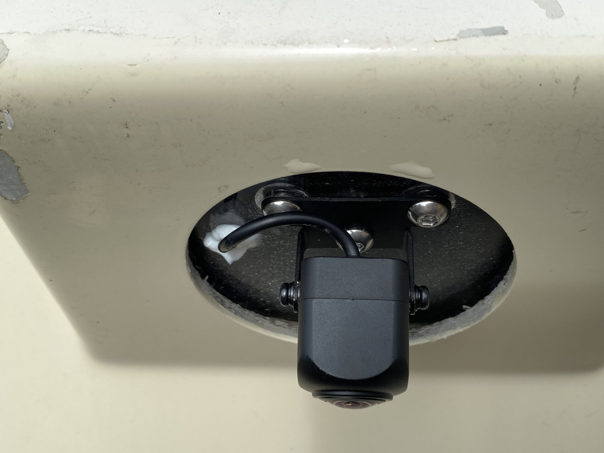
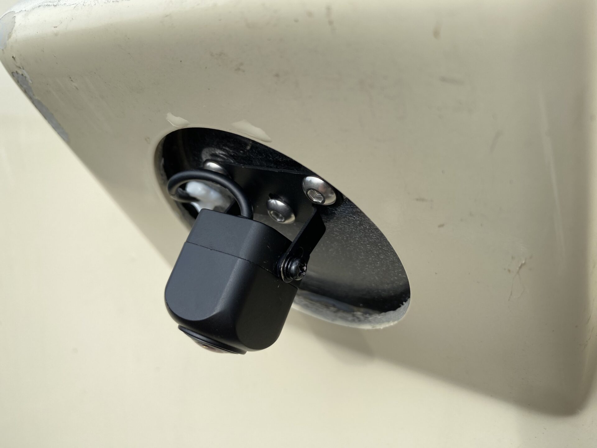
I was intending to mount the camera inside behind the clear cover using the old camera mounting bracket, so I opted for a camera with no IR emitters based on other’s comments about glare. My clear camera cover wasn’t perfectly clear and was collecting condensation. Bret suggested mounting it outside. Great idea. This was really easy – I just drilled through the clear plastic cover for the new camera mounting bracket and then another hole for the video cable. The plug is small so the wire hole is quite small (maybe ~3/16”). The larger diameter end of the connector stays inside. A little silicon sealed up around the wire. I used #10 stainless fasteners with nylon lock nuts on the camera bracket. There are several pics of this install.
The camera’s 26’ video cable has their proprietary small connector on one end to connect to the camera feed, and RCA on the opposite end. So I needed to use that cable, and adapted their RCA end to the coach’s existing coax. I left that long cable bundled and tied and just tucked it in the unused space in the camera bubble. Simple butt connectors got power to the camera from the existing 12v feeds. Snipped one wire on the camera harness to delete the parking guide lines per the instructions. Tucked all of that wiring in the bubble as well.
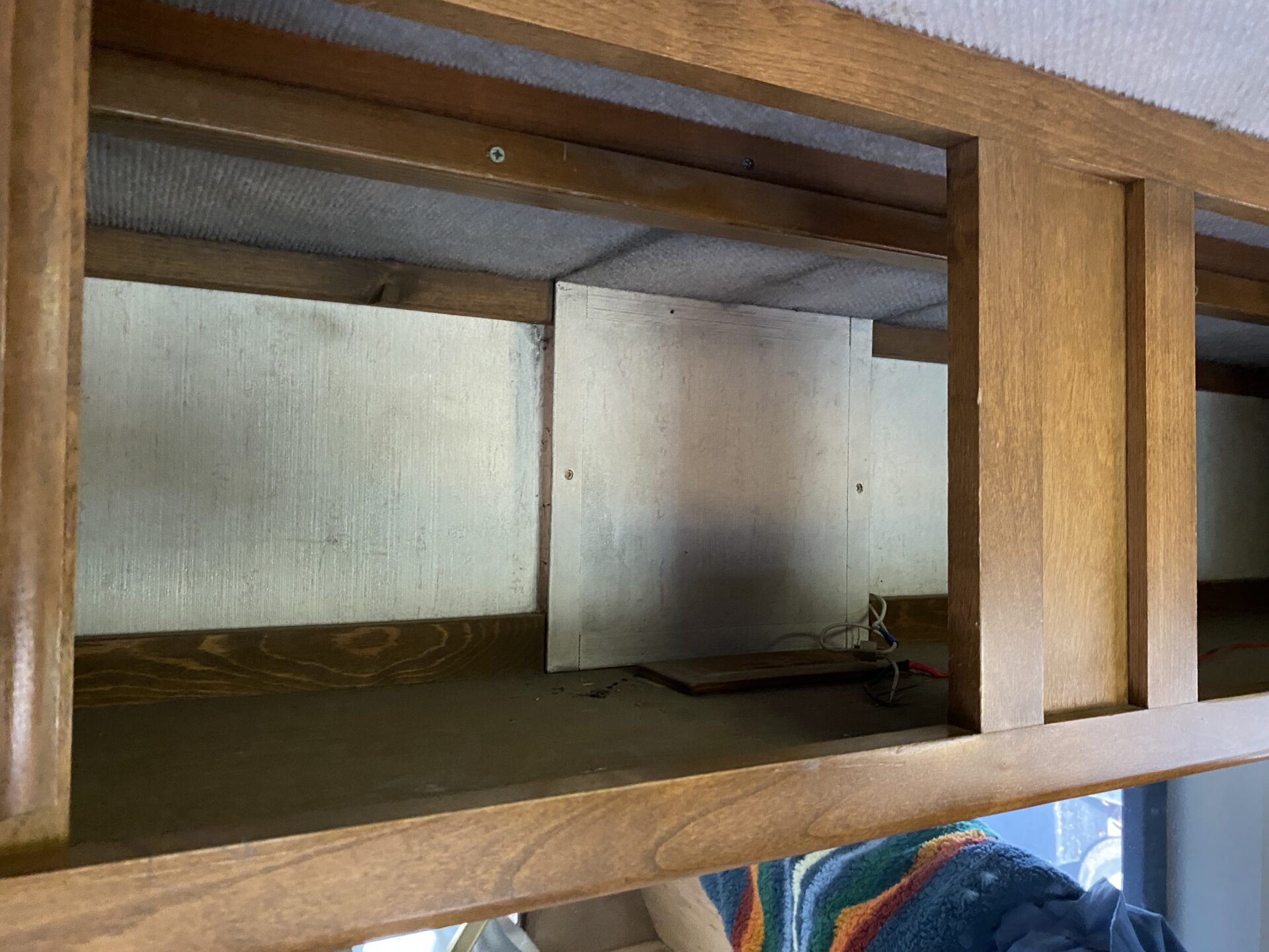
Our rear twin model has a storage cabinet that runs the width of the coach across the top of the rear cap. In the middle of that, there was a roughly 1’x1’ box that housed the old camera system. This was no longer needed and was easily removed (was halfway falling out already). The old access cover fits perfectly over the camera bubble space and holds in securely by friction. Super-easy and I didn’t need to build anything for this. See the pic of this space closed back up.
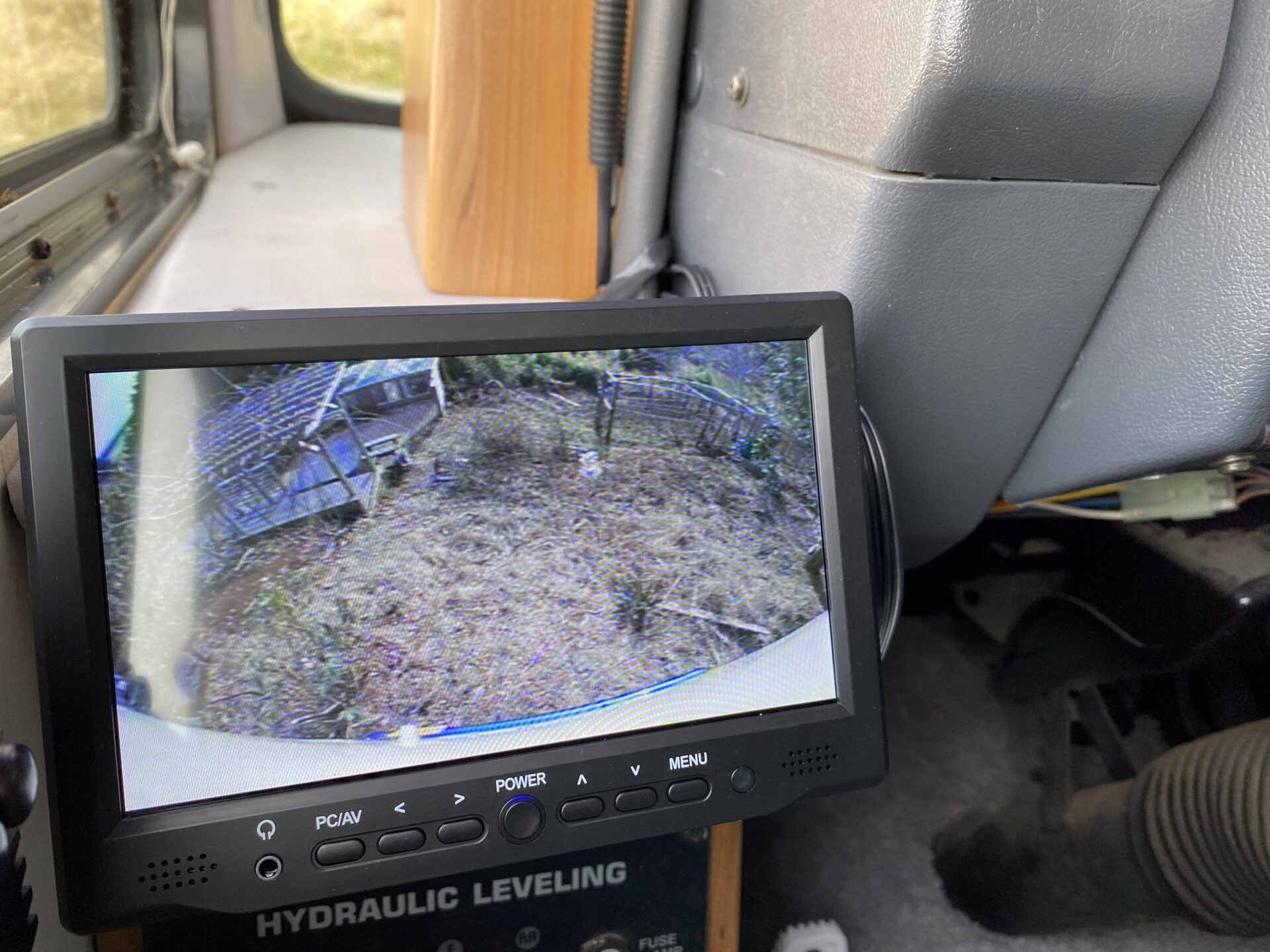
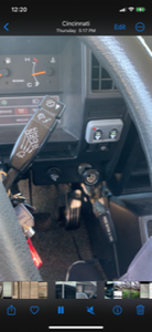
Now up front… Our coax terminates at the driver-side end of the dash, behind a small cover panel. The previous monitor cable ran up the side and kind of tucked in the dash seam over to the middle. Took all of that out which cleaned things up a touch. I decided to mount the new 7” monitor on the wood panel immediately above the jack controls. However, the Trek filler panel that fills the space between the Isuzu dash and the coach body protrudes out from the jack panel by close to an inch. This prevented the camera from tilting up enough – it forced it to point down more than I wanted. So I made a small block about an inch thick, slightly larger than the monitor mount bracket. I attached that to the jack control panel board, and then attached the camera to this block. This extra space allows the monitor to tilt correctly and only added 2 screw holes to that jack panel. I like this location because it is a short glance down from the mirror. See the dash pic – the 2 red boxes show the old and new locations.
I’m not sure if our setup is typical, but our camera system is switched on via a dash switch – see the yellow circle – it’s the top switch. This same switch also powers the digital tach in that small secondary cluster.
Monitor wiring… it came with an input cable taking RCA audio and video to the 1/8” plug on the monitor side. I taped off the RCA audio ends so they wouldn’t catch interference, and then taped the RCA video input to an adapter and then to the existing coax. Tucked most of that in the dash behind the end panel. For power supply – it came with a 110v wall mount supply that converts to 12v. I saved that aside and grabbed an old power supply I had here that fit the receiver on the monitor. I clipped that end and a couple feet of cord from the wall-plug portion. Tossed the wall plug. I could have easily done this same thing with the new one, but I figured I would use the old one just in case I have a warranty issue. The old monitor sourced power from a small distribution block on the outside of that dash end cover panel. I connected to that, preserving the inline fuse that was there just in case… Easy.
At the same time I made a wood cover for the wiring installed on that dash end cover. Ours was exposed and a bit ugly. I’m guessing that was covered originally and our cover was lost along the way. This new cover is barely visible in that same pic, the edge peeks out on the end of the dash. This one slides down using a concealed mounting bracket so no install holes are visible. In the spirit of Trek, it is made from Red Alder grown and made into lumber right here at our place on the Oregon Coast.
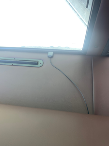
There’s a final pic of the monitor on. The white arc is the end cap, the thin blue line is the bumper, and that pergola is about 20’ away. Mounting the camera this way gives you a great angle for backing.

It is Wonderful How the Trek Family Works
acudoc888(at) gmail.com
Denney had a bunch of parts from his removed vintage Norcold fridge which he offers to Henry cuz Henry, at the time, has a same model fridge. Eventually Henry parts ways with his fridge, (Trek attached) so he brings the parts to the 2023 Quartzsite Gathering and passes them to Bret to offer at the Sunday flea market. At the subject flea market along comes Don and Lucy who grab the parts “Just in case”!!!! Well as luck would have it, in less than two weeks, Don and Lucy’s fridge refuses to light and what to wondrous eyes should occur, but one of the newly acquired circuit boards now solves the problem. That in itself would have been great enough, however a few days later Don and Lucy return to the Quartzsite gathering area to learn that
Juliet’s fridge door, in her new to her 2005? Trek, was on the floor. Greg recognized immediately he could repair Juliet’s failed door hinge
using the hinge parts Don and Lucy had gotten from Bret who had gotten them from Henry who had gotten them from Denney. What a plan 😁
Norcold Overtemp Switch Failure
islandduo(at) comcast,net
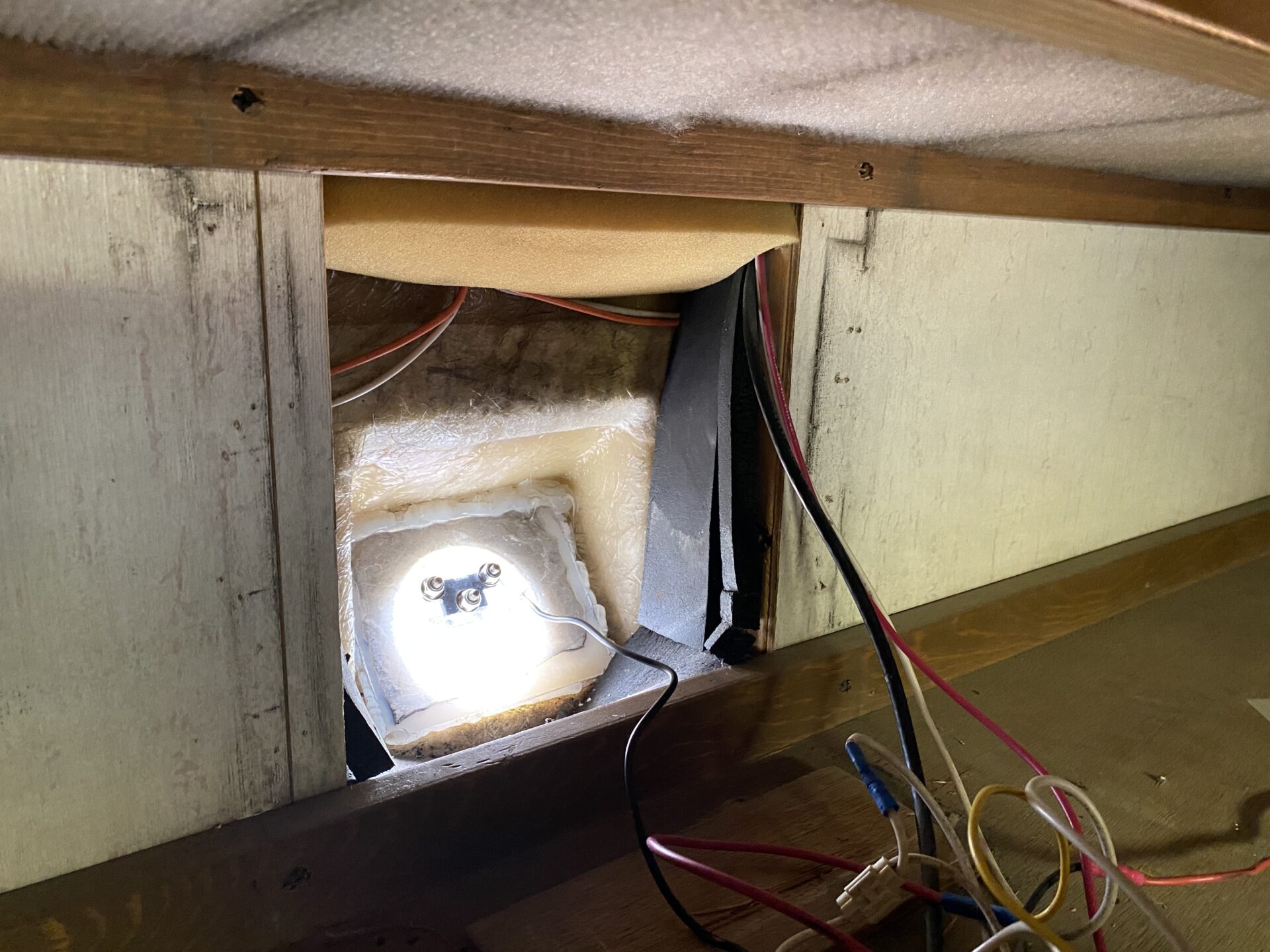
The other day we shut down the fridge to get propane however it would not re-light after all was done. Yup the propane was turned back on, stove burners worked fine. The Norcold model 841R fridge displayed an error code that read “L1 OP” or I suppose it could be “l1op” either way fridge will not light. Turns out the fridge high temp limit switch had tripped (photo). There is a red push button reset on the back of the switch, quick push and all is well. However measuring temps with a heat gun revealed operatings temperatures far lower than the switch’s supposed trip point indicating another failed switch.
We had this same switch fail on us some years back, the original switch had no reset button, but bypassing it by installing a jumper between the two leads got the fridge operation back until we got a new switch. The original switch has a trip point of 378 Deg. F which is only available through Norcold as a kit including the entire heat stack and insulation. Purchase of the Norcold kit was how we fixed the problem back then, however we just stole the new switch from the kit as the only thing bad was the switch, not the stack etc. This time we decided to do some searching for an adequate replacement switch.
This appears to be an adequate replacement having a trip point of 350 Deg. F www.amazon.com/gp/product/B0BF5R5DSZ/ref=ppx_yo_dt_b_asin_title_o00_s00?ie=UTF8&th=1 rather be a few degrees lower than a few higher.
I will be ordering a replacement as the tripping of the switch was unjustified both before and now. I believe this switch was added as a safety feature to shut down the fridge in the event of an overheat (fire).
Update; Near a year later the above switch is functioning just fine, did you notice we now have a spare as well?

Updated/Corrected Alternator Wiring Diagram
rgkreutzer(at) mac.com

Truly High Tech Cruise Control
calpersfatcat(at) yahoo.com
After reading every Isuzu cruise control trouble shooting thread that I could find, I decided that the original ACME cruise control was a lost cause. The steering wheel control stalk looked broken, and I could have started with that, but at the end of the day, both Bret and DickK felt that the thing is not worth saving so I decided not to invest the time in attempts to repair.
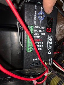
I ordered the Dakota Digital GPS Speed Sender, the Dakota Digital cruise control (Rostra) that works with it and the Dakota Digital external GPS antenna that is also available. I bought the equipment from Summit Racing because they had everything in stock. It came to $632 including Ohio Tax with free shipping.
I am not a mechanic and do not understand electronics at all. Zero. I have to watch Youtube Videos every time that I need to use a multimeter because I can never remember which setting to use for what I am working on at the time. If I can do this, probably anyone can do it.
That said… I projected two full days to do the install. I already had the dashboard apart in order to FINALLY finish the dancing dashboard shake issue, so that was helpful.
It took me exactly two 8 hour days. I installed and uninstalled the servo unit two times before settling on the final location, to the front of the front passenger side tire. I am still searching for that heavy, stiff plastic that Safari used on the bottom of the Isuzu Treks (struck out at the big box stores) because I need to make a splash shield for the servo unit to protect it from tire spray.
It seemed like the drivers side of the engine compartment would be the best location because, logically, the control unit would be on the drivers side of the cockpit and I knew that I was limited by wiring harness length. After installing it on the drivers side of the engine compartment, I sat on the ground inside that wheel well there and stared and stared at that exhaust manifold and of course, the turbo, thinking about all of the heat generated on that side of the engine. …
At the end of the day, I chickened out, removed the servo, and located it to the position depicted in the photos.
As it turned out, the new location allowed for a nice slow, smooth loop from the servo unit over to the accelerator linkage, across the top of the fuel intake plenum (that’s what Porsche calls them, unknown what the Isuzu name is for it). The wiring harness goes directly forward, then up and backwards through the existing grommet in the steel spacer that connects the end of the dashboard to the outside skin of the Trek. The wiring harness then turns inboard and terminates right in the middle of the dashboard, adjacent to the ACME HVAC mixing box.
I pushed the “Eco” switch out of the dashboard and secured it underneath (out of sight), used a Harbor Freight plastic weld kit to put an ABS Plastic backing in it’s place, and then drilled holes in the ABS Plastic to affix the dashboard control switch. The wiring harness’s joined with several inches to spare. Had I used another steering column stalk control, I would have had to extend the wiring harness myself. I am not crazy about the way that the switch looks on the dashboard, but beggars can’t be choosers.
So how does it work?
Perfectly.
In retrospect, I’m glad that I couldn’t find a local shop to do the job. When/if it breaks, I’m pretty confident that I can do the repair to get it functioning again, and/or simply order the replacement part. I am a bit skeptical of the strength of the “chain” that connects the servo cable to the accelerator, but Gabby believes that it is super strong. I will probably fashion a battlefield remedy out of thin steel wire since I already have the hydraulic crimper that I used to make the battery cables, then if the thing fails during a trip, I can quickly swap in my bulkier but stronger linkage to get us home.
I have used the cruise control a half dozen times (for 12 miles at a time), and I am amazed how well it holds the speed at 55 mph. I kind of felt that I would need to run about 63 or 64 to keep momentum up for long grades, but that has not been the case. Cincinnati is not mountainous, but its certainly not flat.
I hope that this post helps someone out in the future. I will certainly do anything that I can do to help another Isuzu Treker who gives up on Acme.
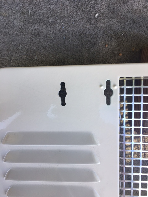
Water Heater Cover Retrofit
sulaik(at) yahoo.com
I lost my water heater cover. I bought a new one but the key hole did not match up and found out that they don’t make my cover anymore. So, I had to do a retrofit. The following pictures pretty much shows what I did to make it work. I wrapped insulated wire around the key so that if it got loose, at least the wire would hold on to the cover until I can fix it again. Looks tacky, I will keep trying to make it look better. The blue tape on the finished panel is to protect the paint from getting scratched. Note the cover did come with the outside frame and I could have replaced the whole thing. That was a lot more work. The current frame is like cemented in there (hard like a rock) and I did not feel like breaking all that up. So, I went this route.


And the best for last:
Redneck Mini Blinds For Your Trek
gshindler64(at) earthlink.net
Especially economical for the windshield

Remember the I-Trek Infoletter is created using content submitted by you people, the owners and users of these fantastic machines. In my opinion there is no better way to help the owners and users than to share between all of us. PLEASE feel free to submit anything that you believe might be helpful to other I-Trekkers to me at islandduo(at) comcast.net at any time and I will include it in the next infoletter.
I apologize for the lateness of this issue.
Bret